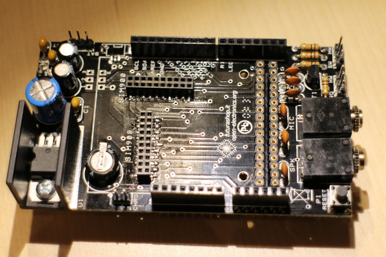
Building the Open-Electronics.org GSM/GPRS Shield V2
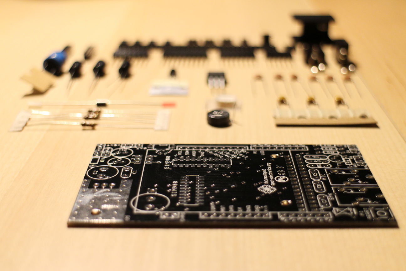
I got one of these SIM900 based GSM Arduino shields and decided to write a little step-by-step guide of building this shield. For schematics and the official documentation have a look here.
Happy building!
-
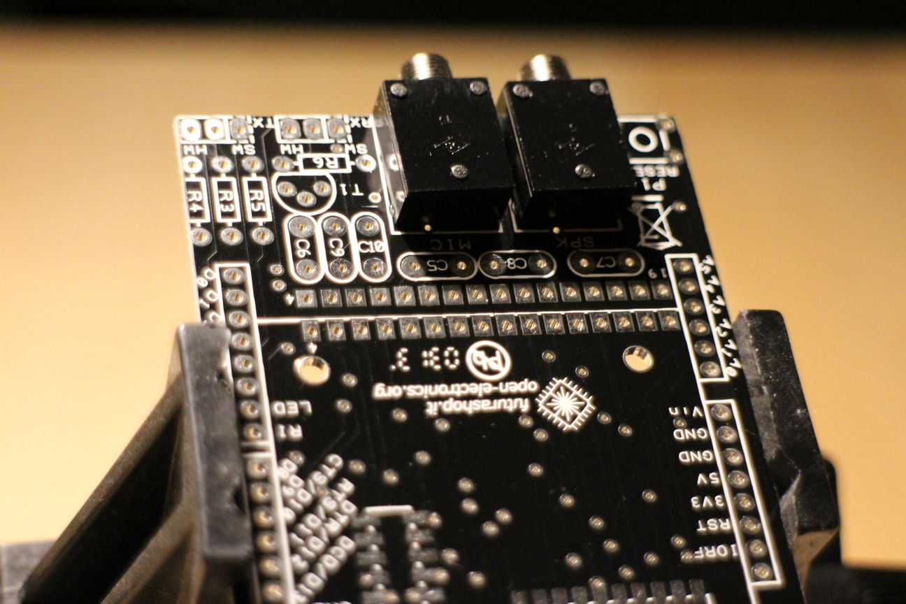
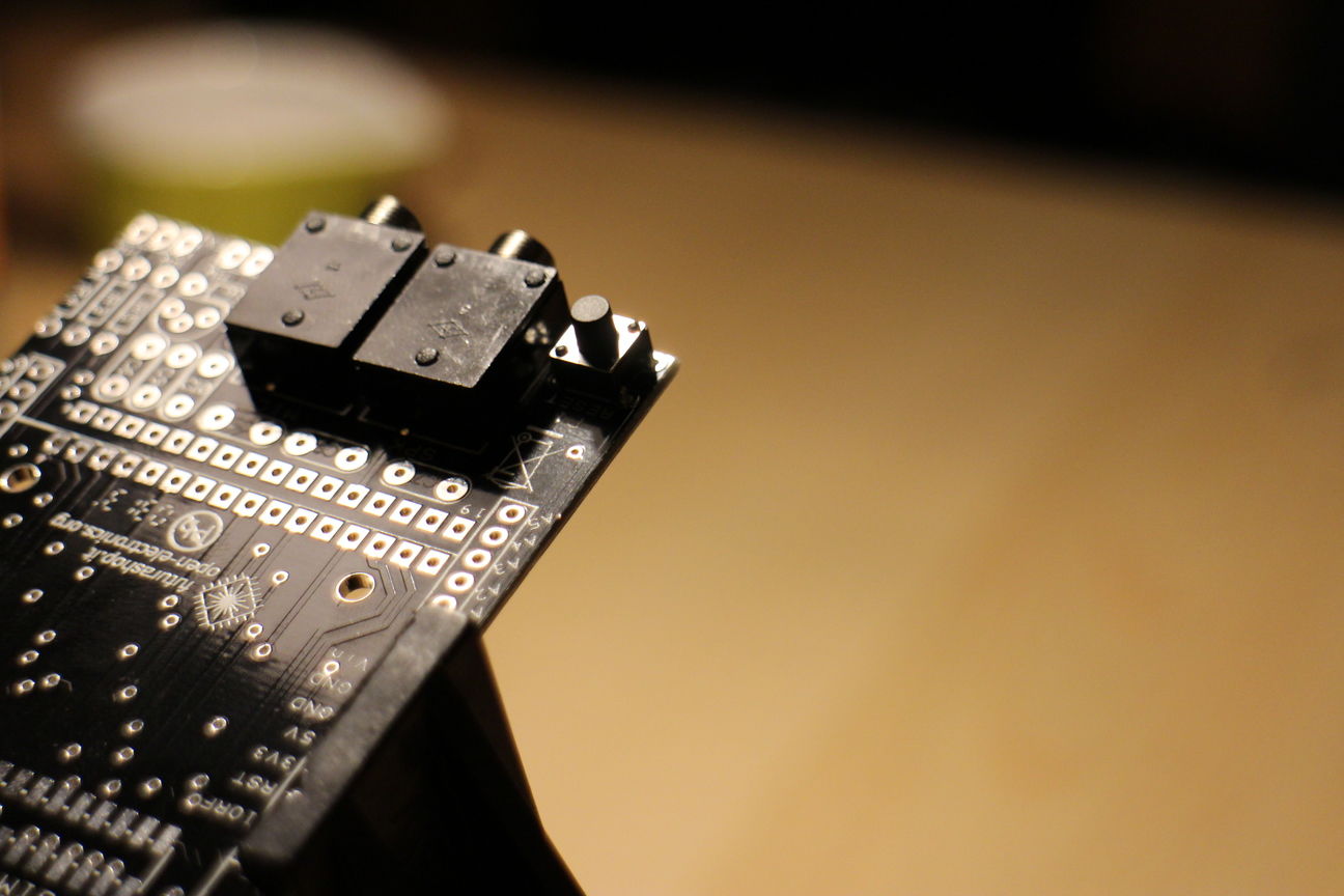
Lets start by soldering on microphone and speaker jacks:
-
Clip the two separate jacks into place, you might need to adjust the pins a bit to make them fit in the holes. Then grab your trusty soldering iron and solder up those connections
-
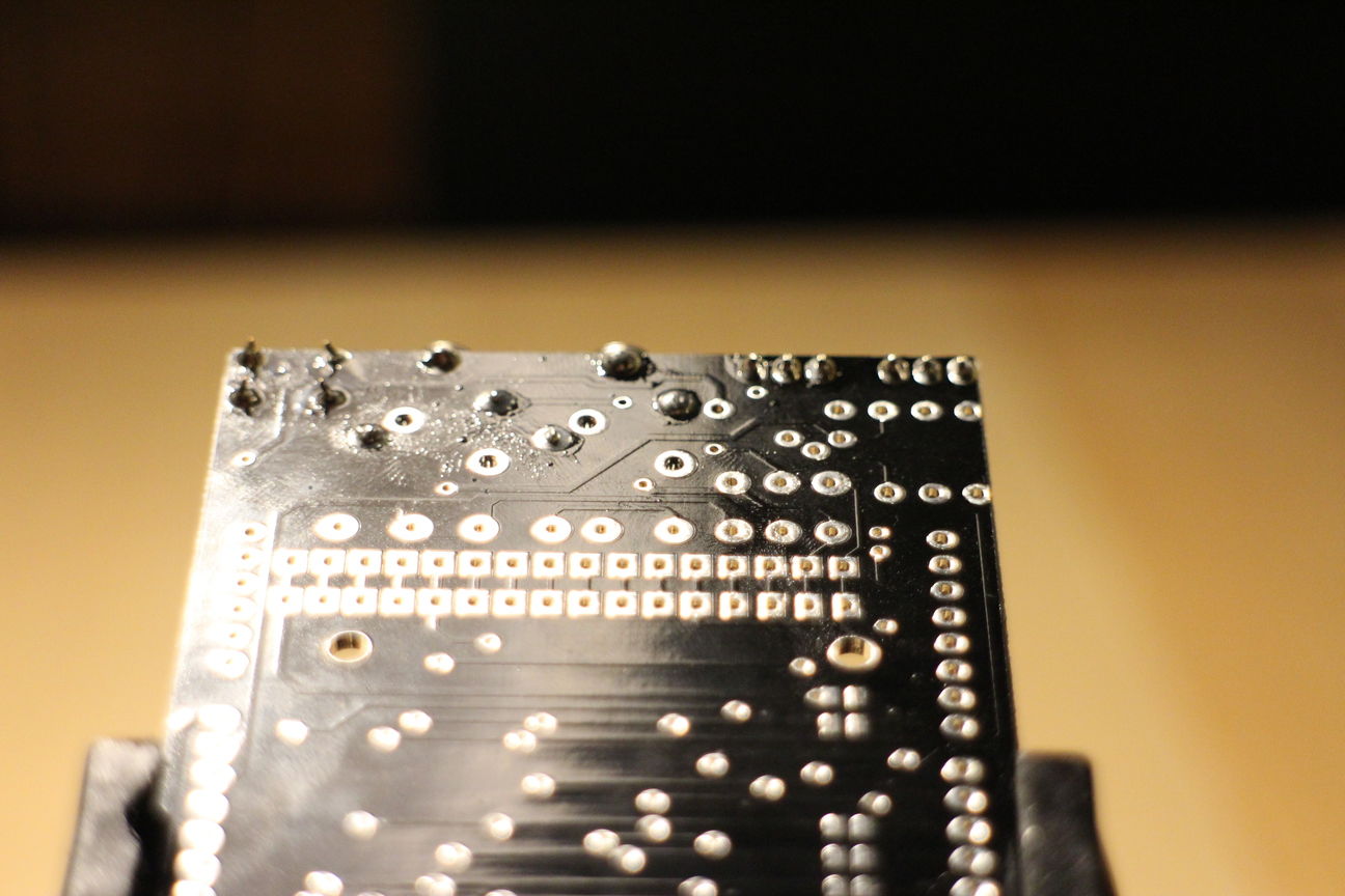
Next lets solder on the reset button:
-
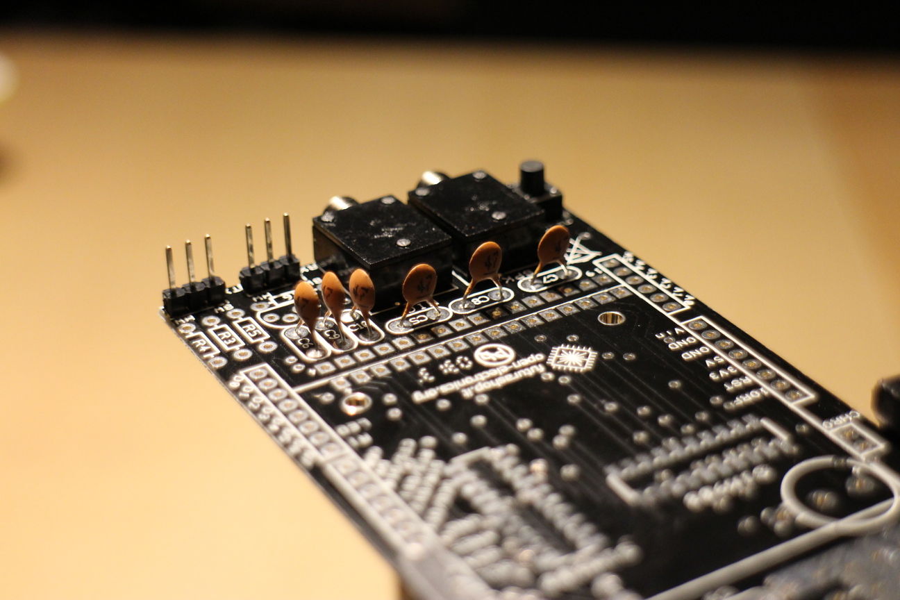
Solder on the 2 jumpers next to the mic jack:
-
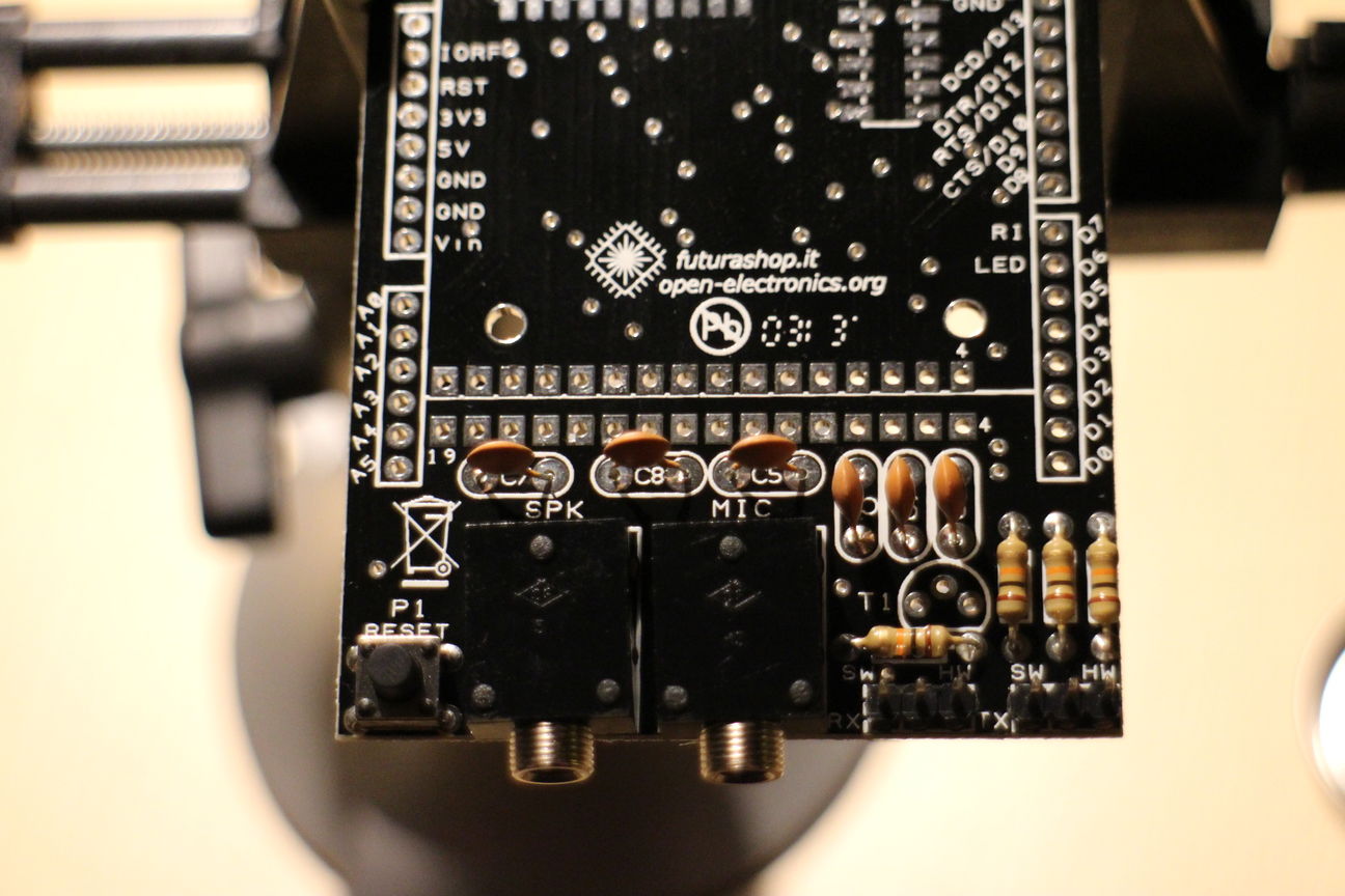
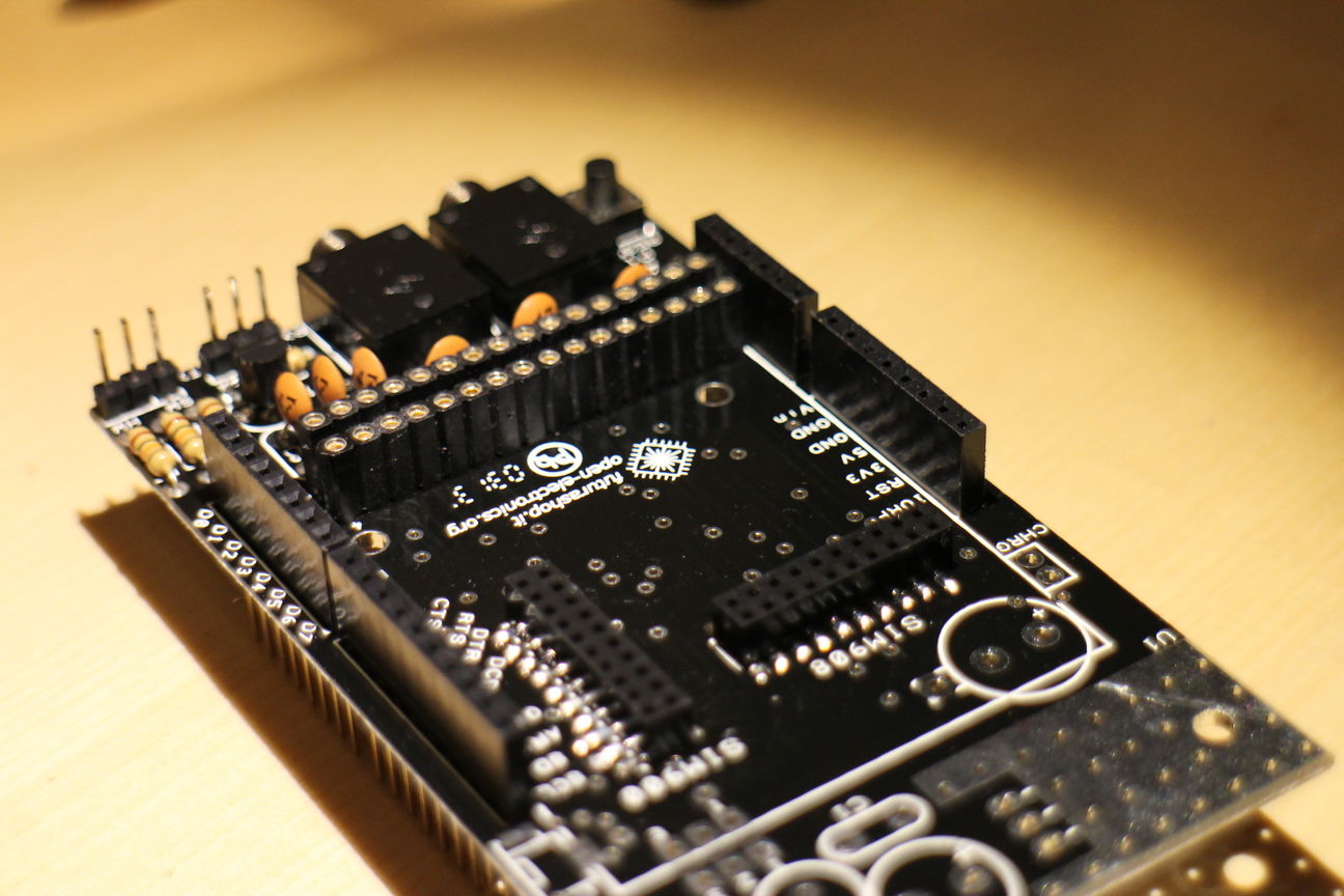
Now lets solder 6 Ceramic 47 pf Capacitors marked C5-C10:
-
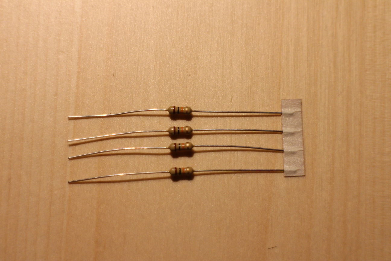
Locate R1-R4(mine were labeled R3-R6), these should be 10K Ohm Resistors(Brown-Black-Orange):
-
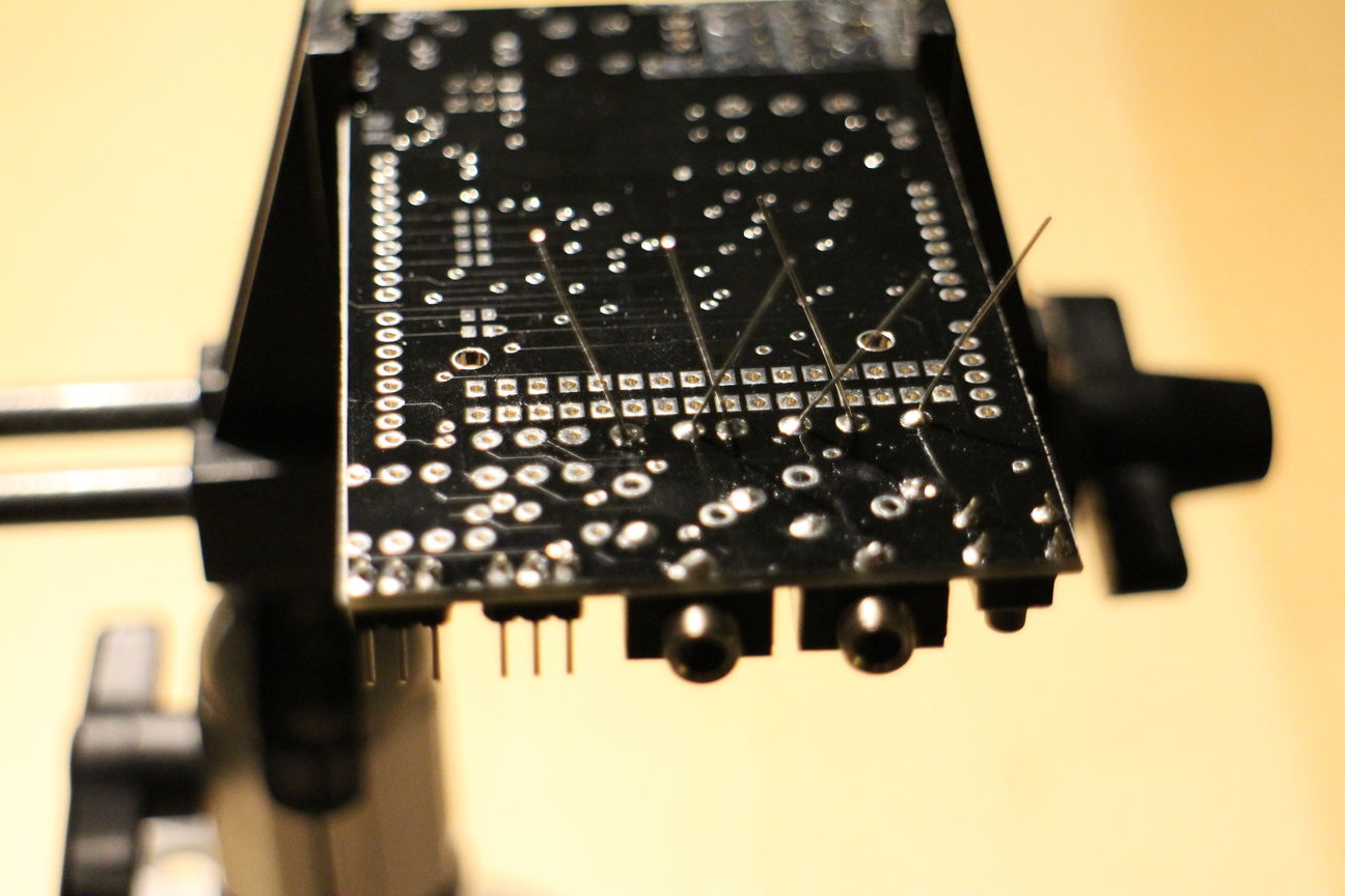
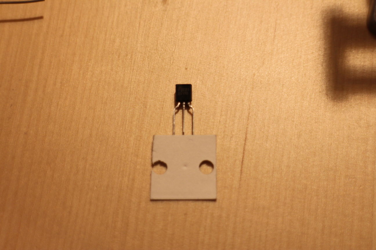
Next find the BS170 MOSFET and thread the leads into the holes associated with T1:
-
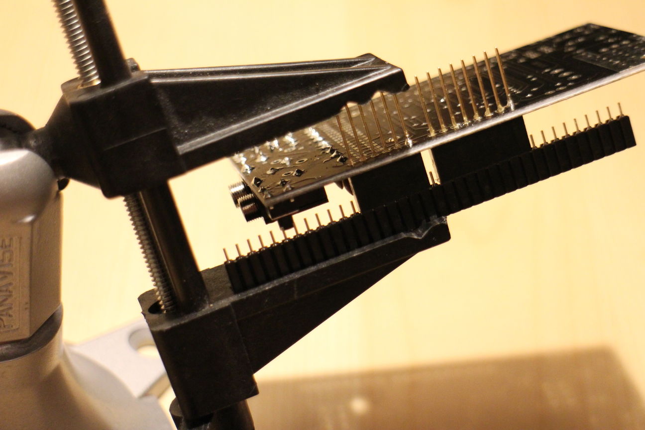
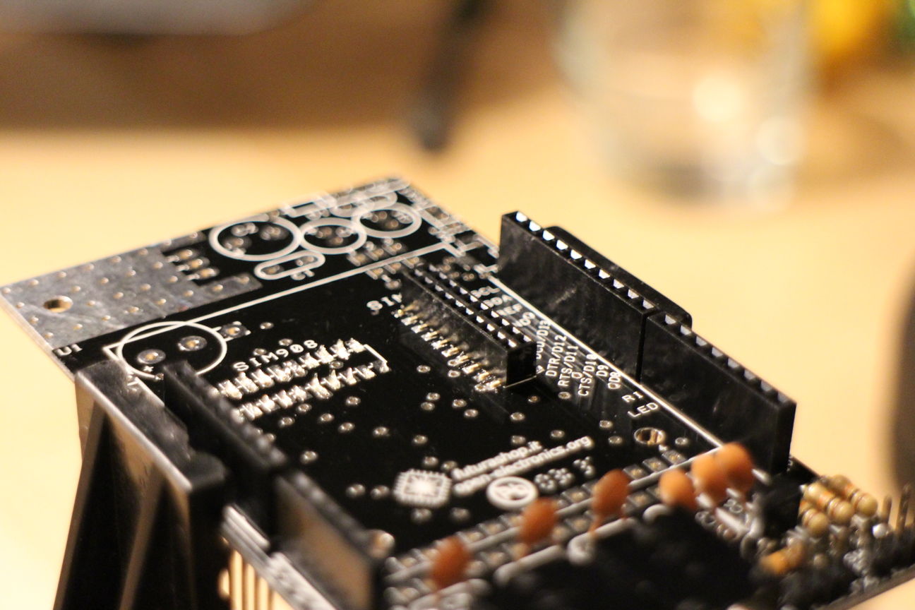
Attaching the Arduino headers, for this you need to be careful to attach them straight and square, otherwise you'll have trouble attaching it to your arduino.
-
I started with the pins on the side of the reset button, I used some extra header to join the two header sections together and put it into my panavise. First I soldered in only one pin of each header:
-
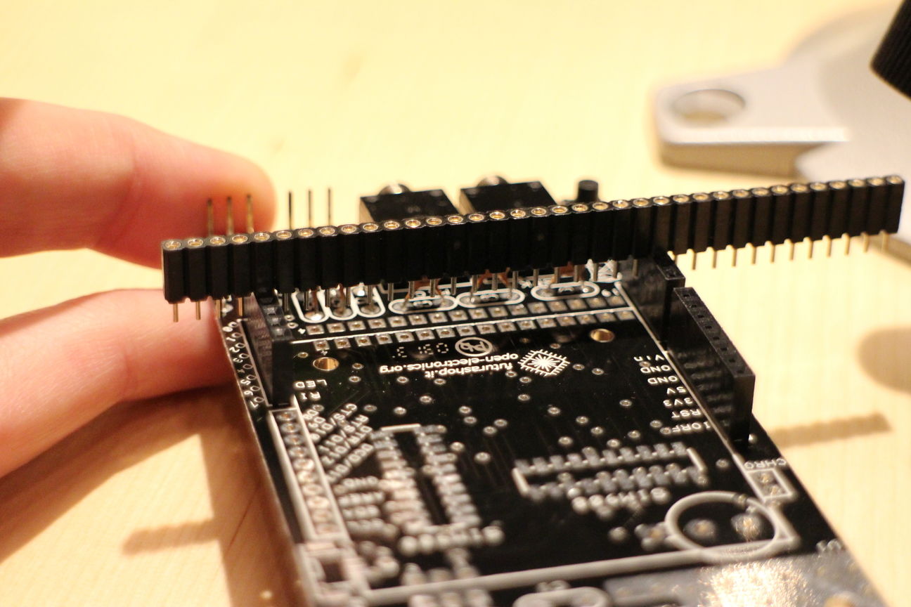
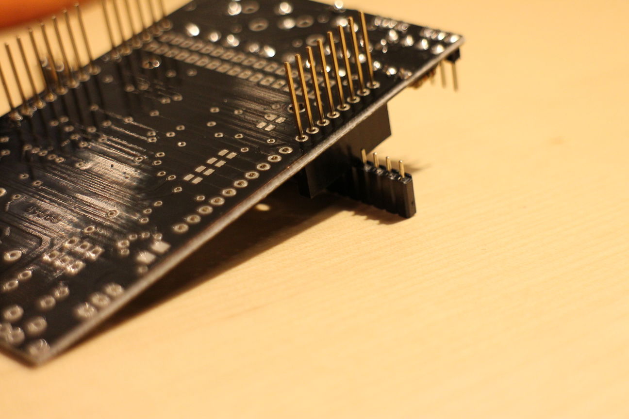
Then, since on the other side it is non standard spacing and therefore the trick of joining the two heads together with a third doesn't work. Instead I used that third header as a crossbrace from the one side to the other. Yet again I only soldered in one pin on each header:

-
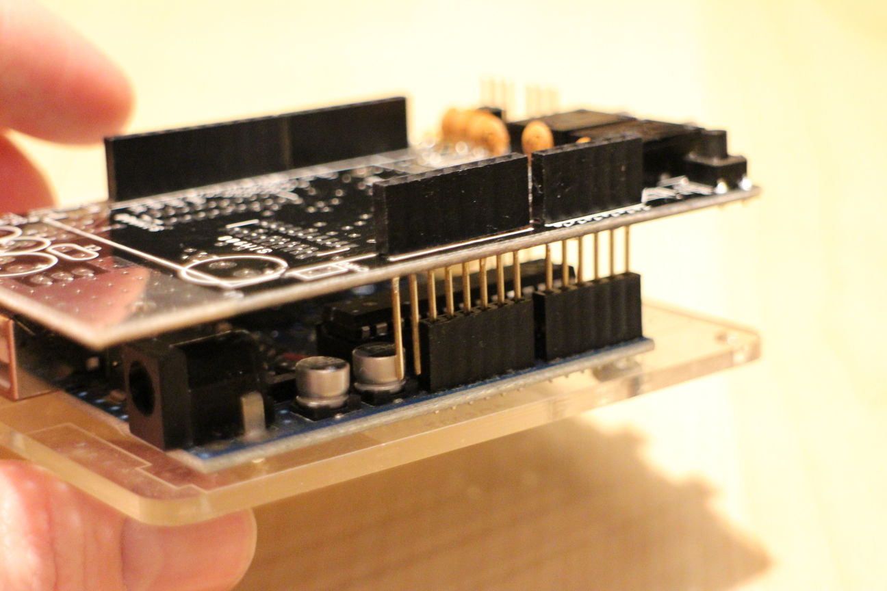
Now before we solder in the rest of the pins, lets double check that everything is square by plugging it onto an actual arduino:
-
If everything checks out, go and solder in all the pins. If not, now you have a chance of reheating and reseating the headers:
-
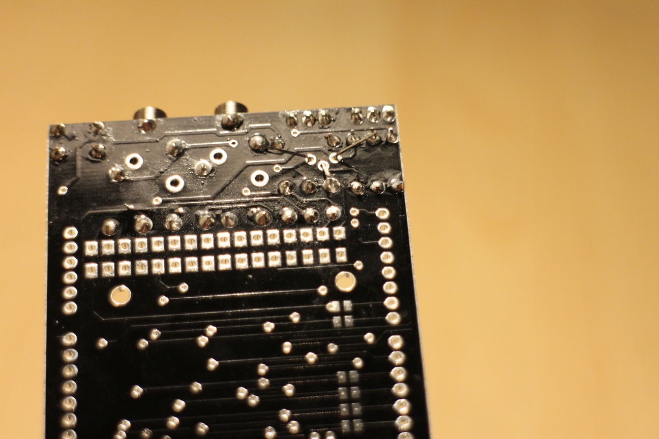
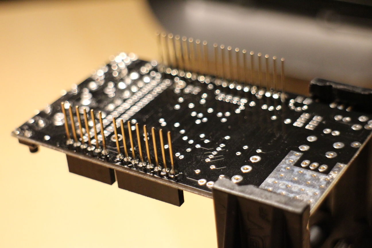
Before we continue on to the other easy parts, lets solder on the surface mount headers for the sim900 and sim908 modules.
-
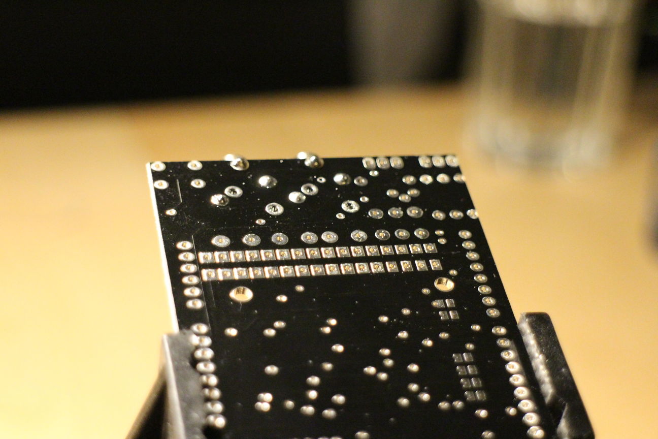
For this I applied some flux paste onto the pads, then aligned one of the headers and soldered on one end pin, making sure it was straight:
-
Then follow by carefully soldering all the other pads. Make sure its clean and none of the solder bridges two pads.
-
Next lets solder on the rest of the through-hole headers, again make sure that these are straight as this is where the regular size SIM900 breakout will mate:
-
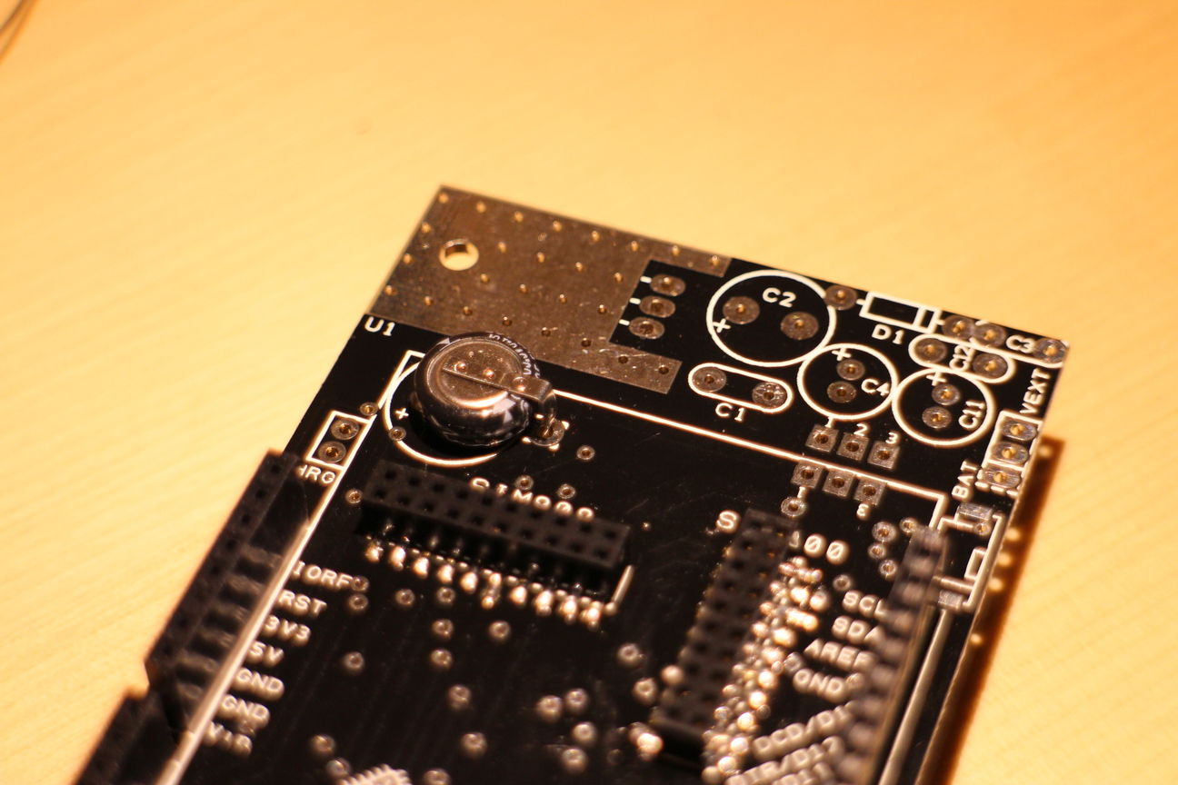
Now lets tackle the unlabled capacitor just above the SIM908, according to the data sheet it should be marked CRTC. Clip it in place, making sure the negative lead, has a tiny minus sign stamped on it, faces towards the center of the board:
-
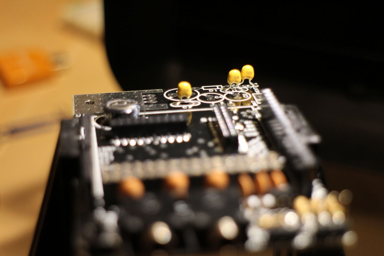
Then continue by adding more capacitors, this time C1, C3 and C12. These should all be 100nF, probably labled something like "104":
-
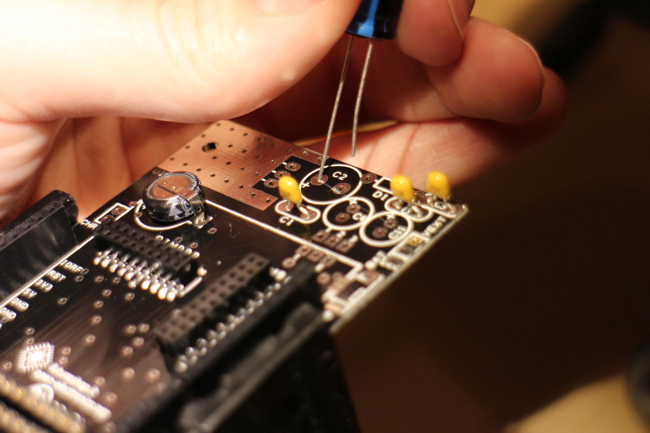
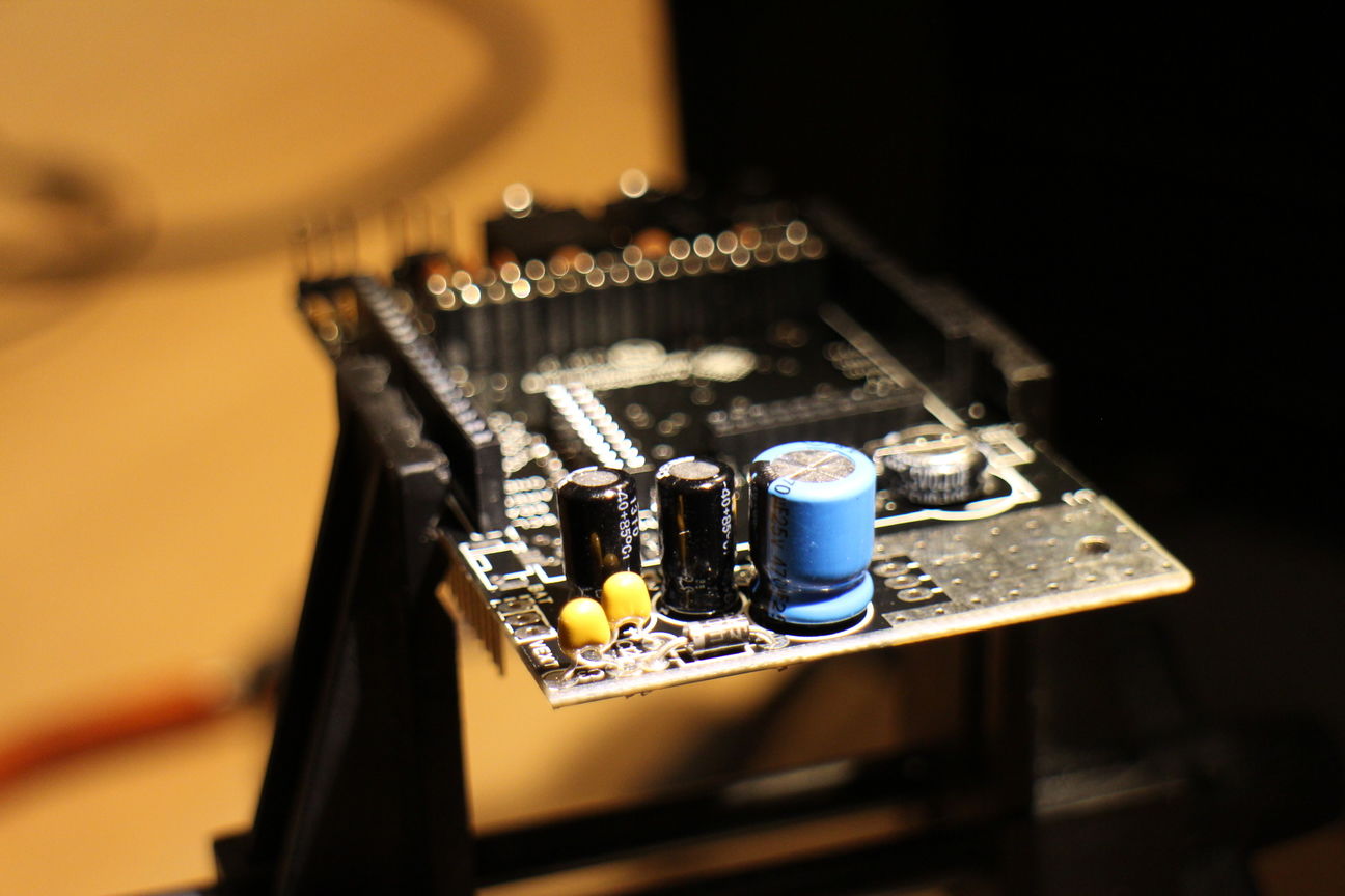
Next locate and solder on C2, C4 and C11. C2 is a 470uF Capacitor. C4 and C11 are both 220uF capacitors. Make sure to get the polarity right, the longer lead has to go through the positive marked hole:
-
Add the 1N4007 diode to D1:
-
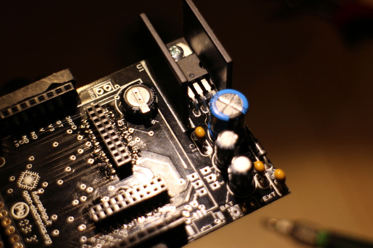
Finally lets put on the big MOSFET and heatsink, first approximate the bends the need to be done to the MOSFET and then thread the screw through the MOSFET and the heatsink and screw it down. Then solder the connections:
-
Almost done, to finish everything off, lets add headers for the Battery plug(its a surface mount, pain in the ass. Also optional depending on whether you're plan on using a battery or not), the Vext and the CHRG headers. I failed at attaching the Battery plug, so I guess I'll be running on external power =)