Security Camera Routing...

Recently I was asked to install a set of security cameras. Having installed security cameras before I figured this wouldn't be a hard task. Get one of the cheap Swann or similar security camera DVRs and just run some wire. This is simple and straight forward. Except not when you need to put wires through walls and have it all look nice and neat. Usually putting a wire through a wall isn't an issue, drill a sufficiently large hole and shove the wire through it, but these cameras need two wires each with relatively large plugs on the end. This would call for a pretty big hole. Instead of doing it the easy but ugly way, I decided to try to feed the signal and power through cat5e, routing it to the destination and then break them out again. Since cat5 contains 8 signal wires, I figure I can route 3 signal channels and power through the same wire. That way I only needed to pull one wire through the wall.
This post is a quickly thrown together log of my approach, my difficulties and insights.
Basic layout
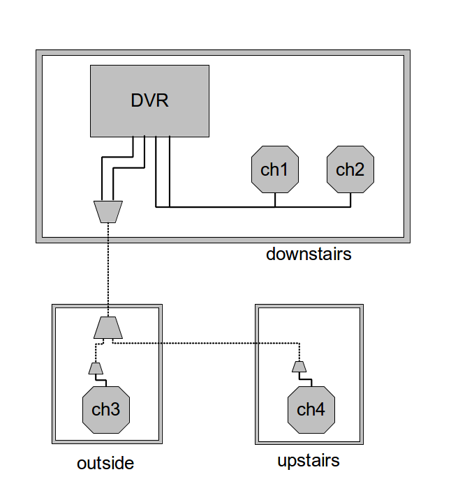
There is a DVR in the main room, with two security cameras in the immediate vicinity of the DVR, and then one outside and one upstairs. The dotted lines in the above diagram indicate runs of cat5 ethernet and the solid lines each indicate the combination of signal and power wire. The first two channels are wired with the provided straight through cables. Channel 3 and 4 are passed into cat5 ethernet cable at the DVR, then passed through various walls, then split, passed through more walls and finally broken back out into signal and power.
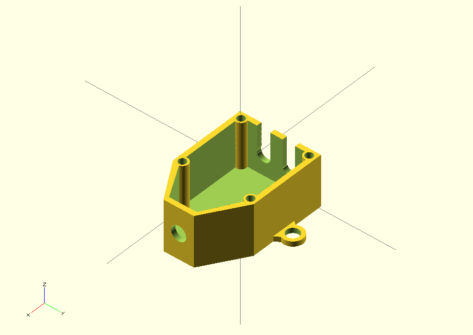
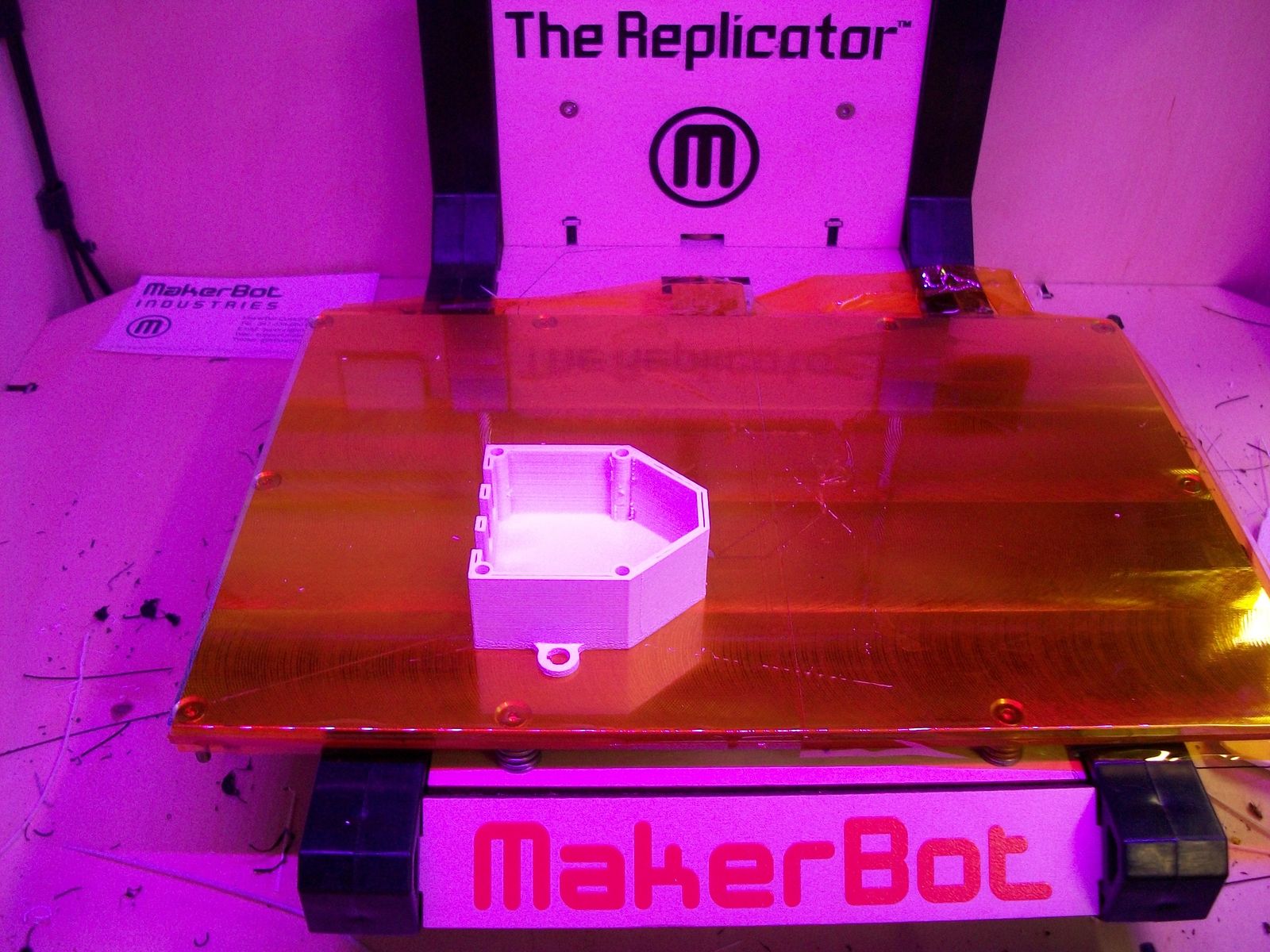
I designed Each of these junction boxes in OpenSCAD and then printed using a Makerbot Replicator I. The OpenSCAD and STL files will soon be available on Thingiverse.
Lets start with some CAD and 3D printing:
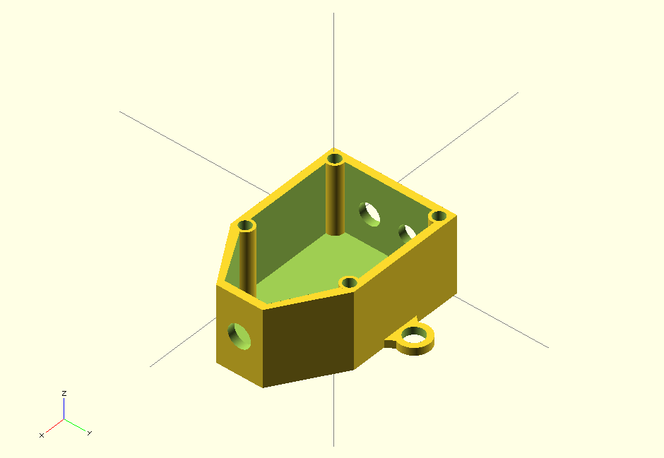
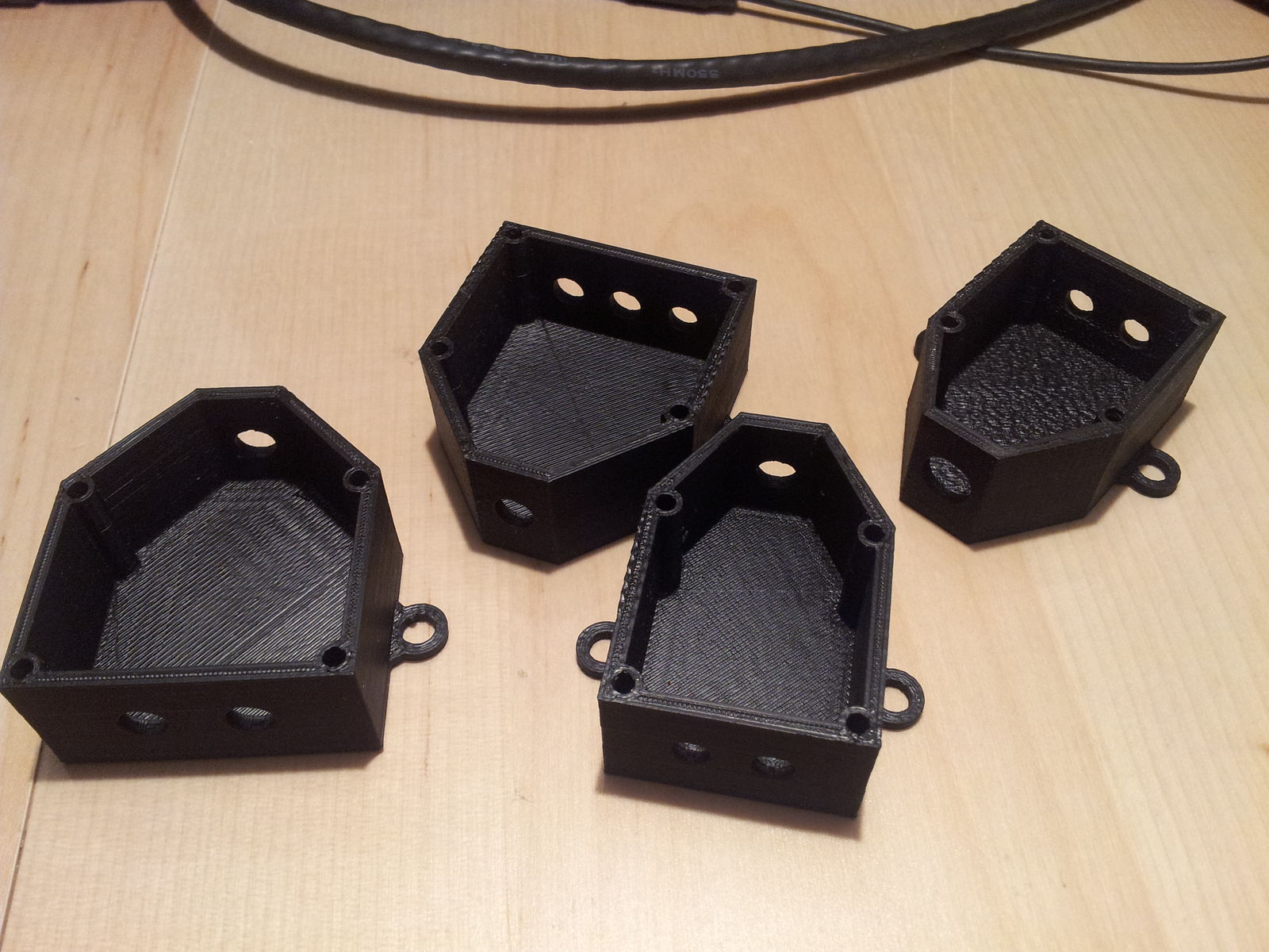
I started with a very simple box design, with one hole in the front(for the cat5) and two in the back(for signal and power).
I then proceeded to print one of these for every junction point along the setup
- 1x Origin box(feeds 2ch & combined power into cat5)
- 1x Splitter box(splits ch3 & ch4 and power in two)
- 2x Remote-End boxes(splits cat5 back into signal and power).
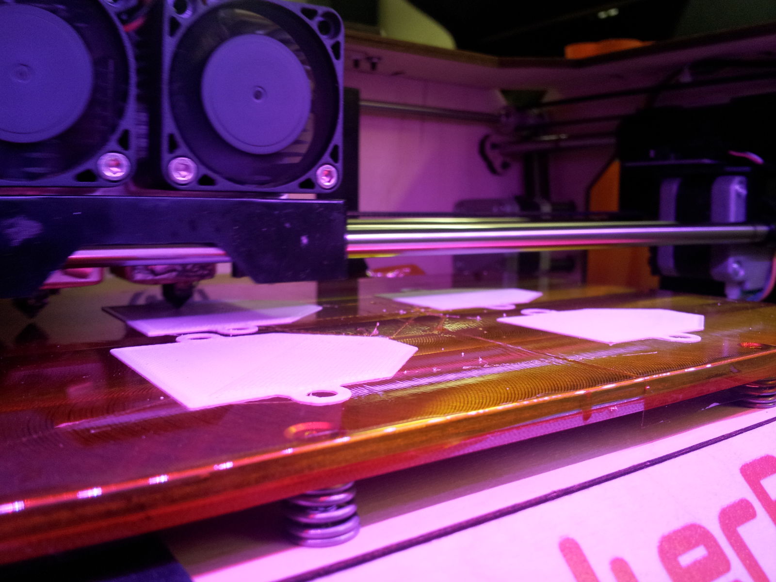
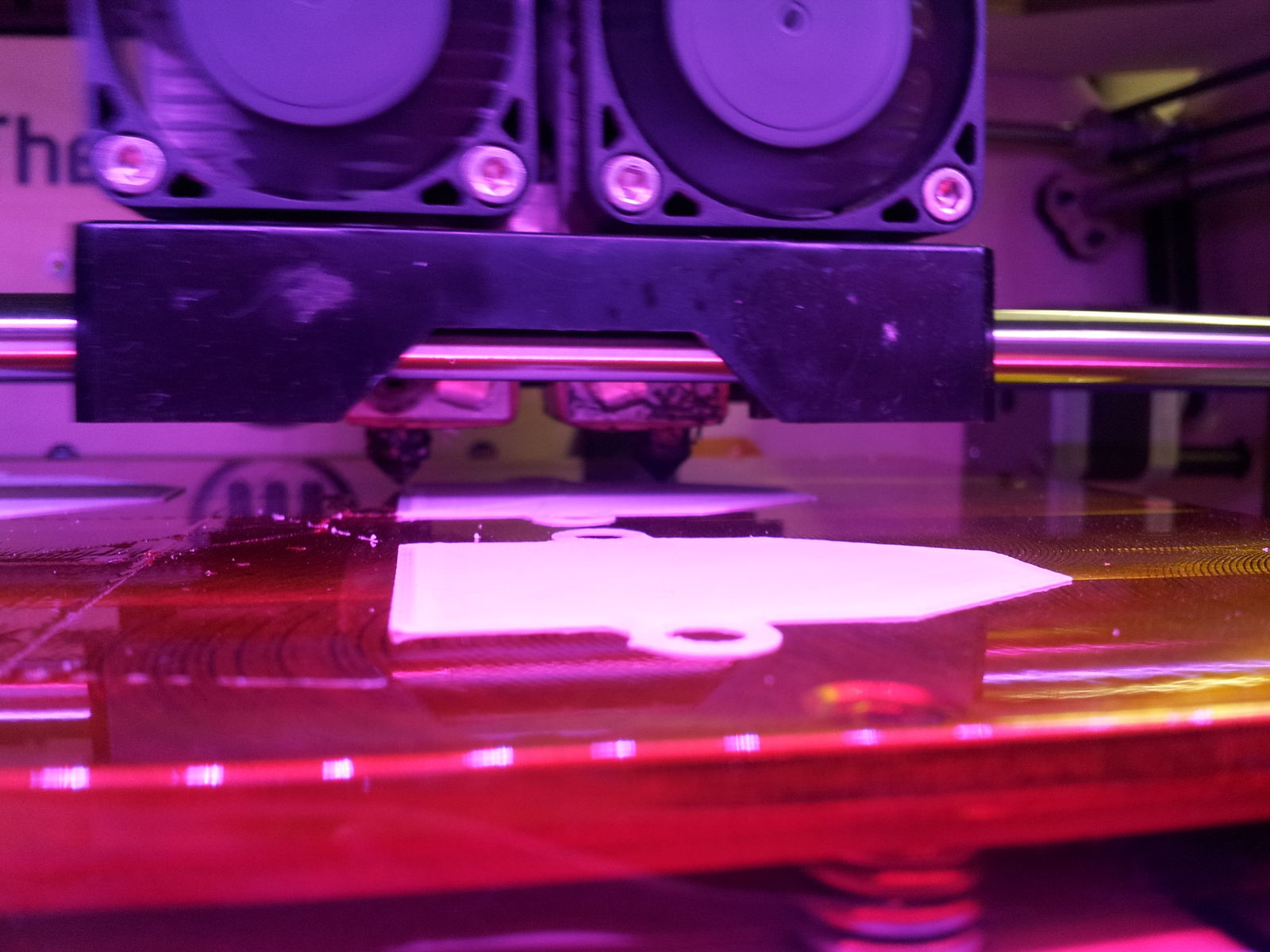
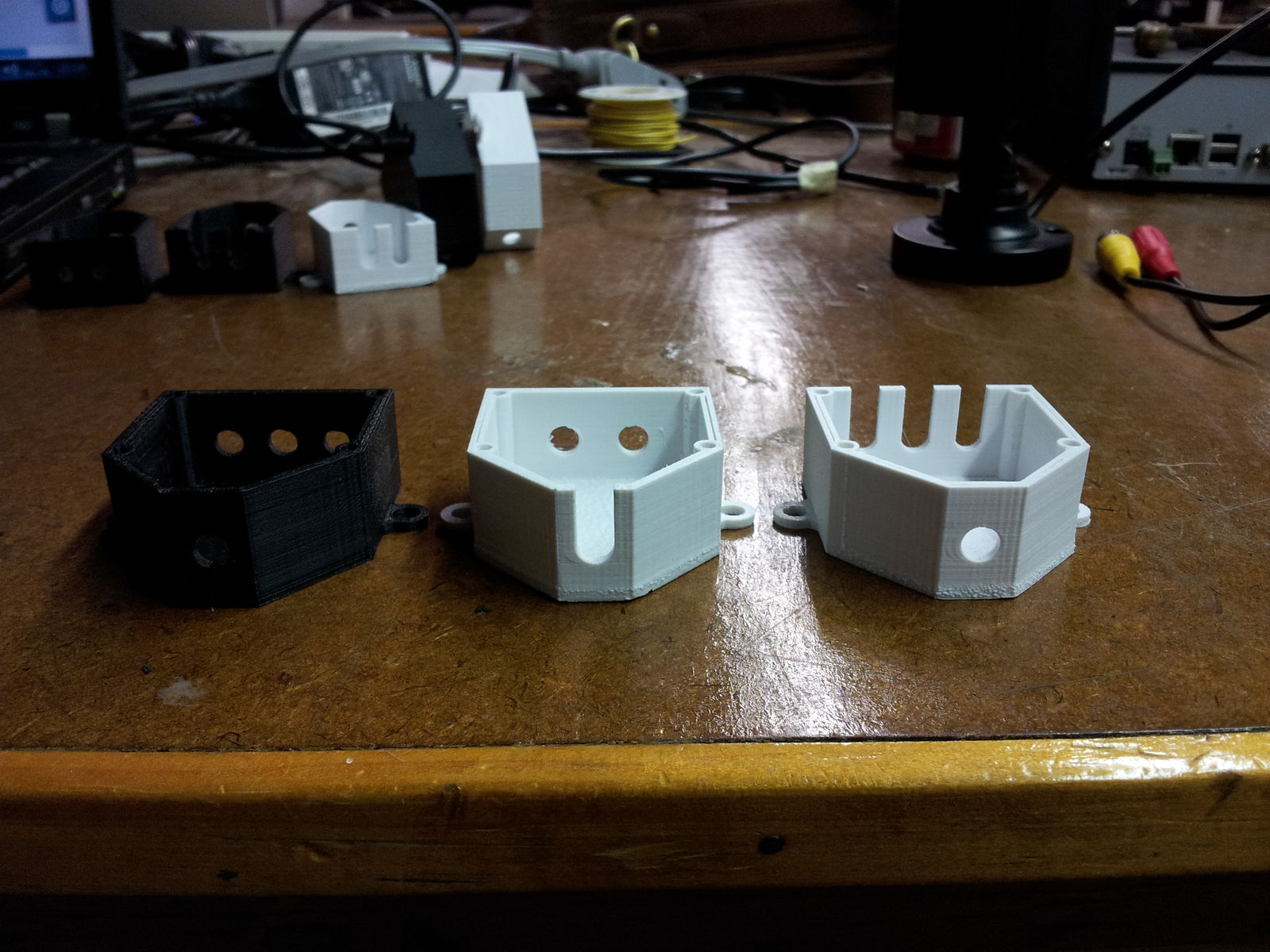
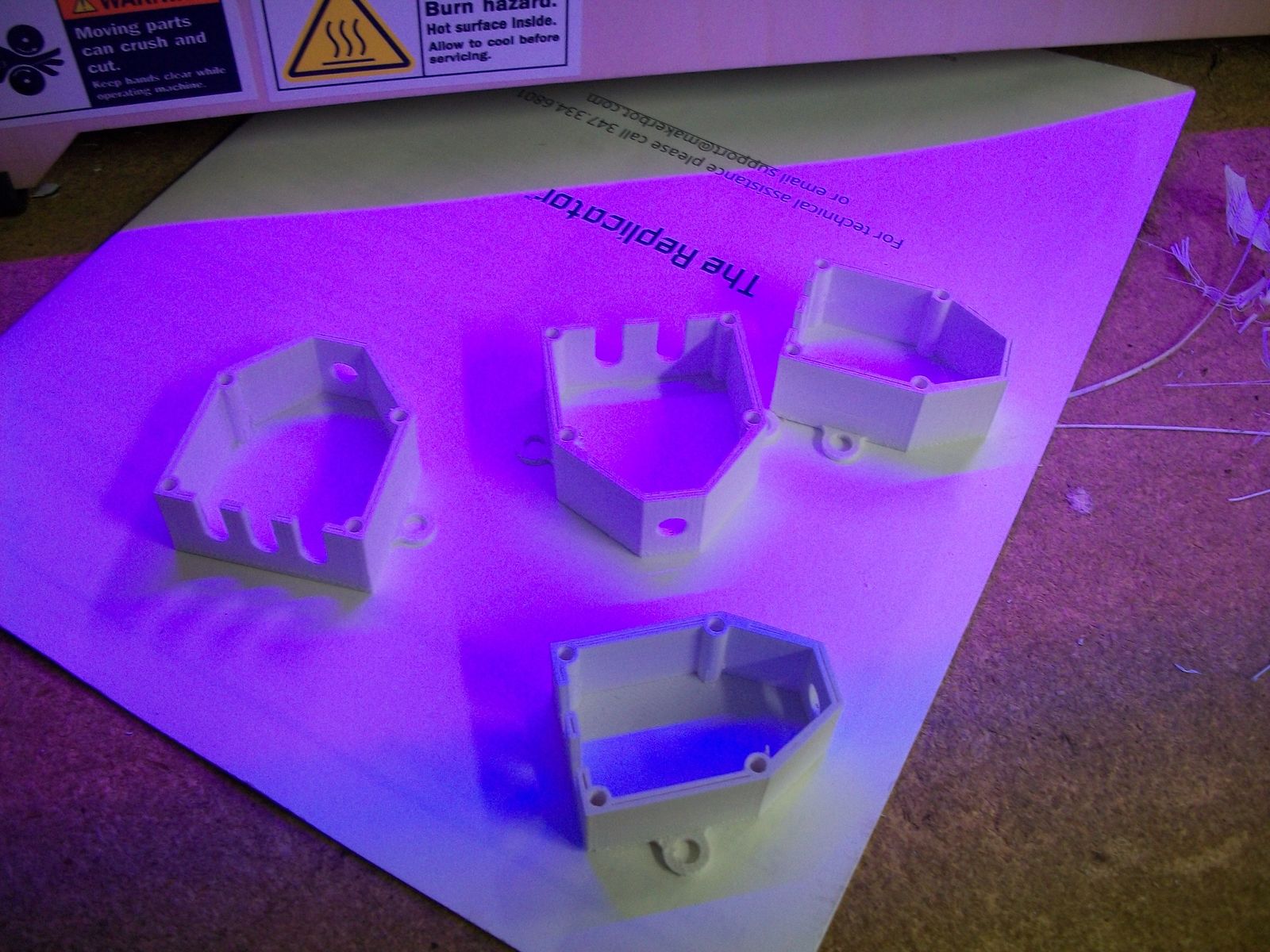
After much time in calibration and persuasion of the 3D printer i was quite happy with the resulting boxes:
Next I soldered together some screw-down terminals on a circuit board and cut it to size
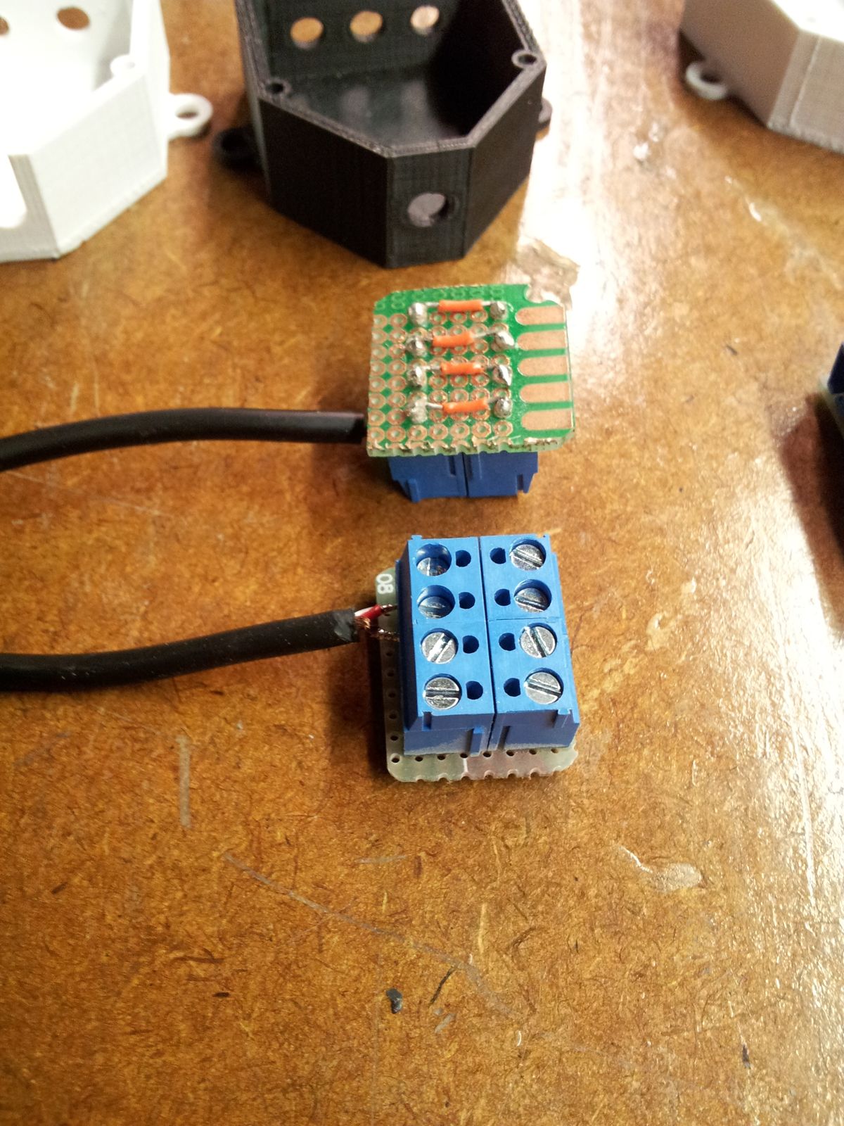
Assembly Troubles.
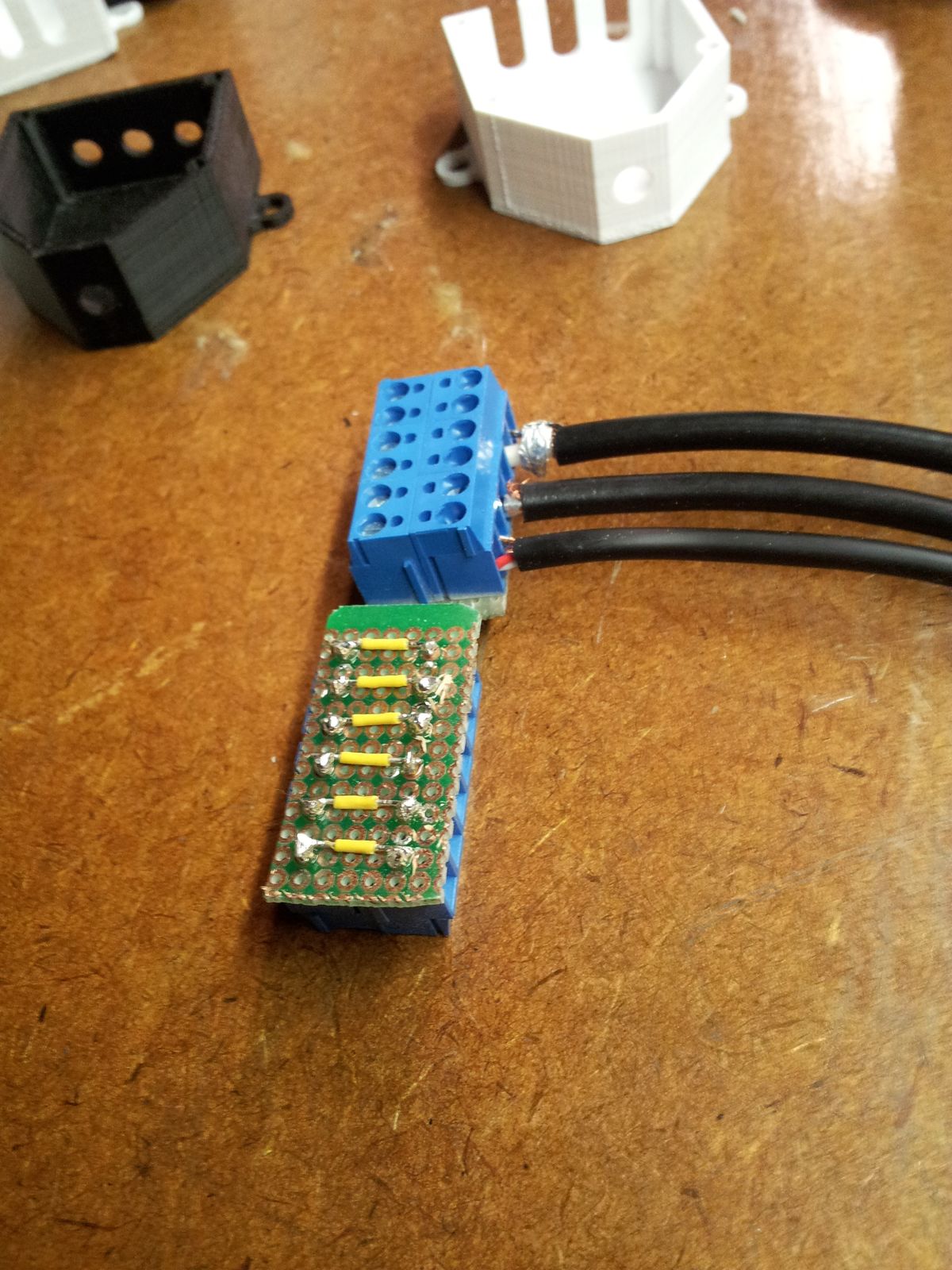
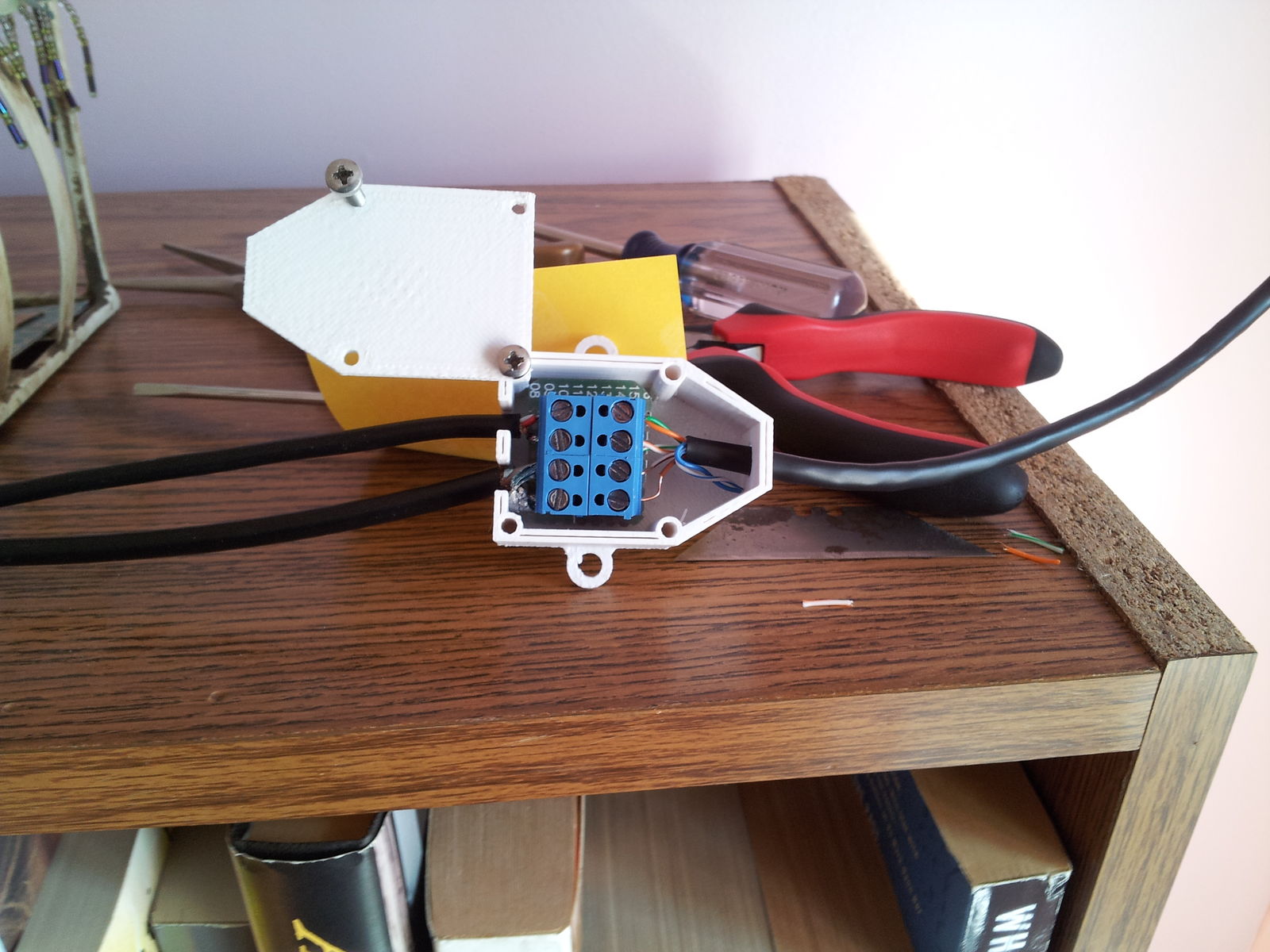
Turns out that getting the right wires in the right places in such a tight space can be quite a challenge. Also considering that I will have to put these things together in a hurry with just a screwdriver and on the floor/ceiling/wall, instead of on a well-lit workbench with a full set of tools, I decided to redesign the boxes a little bit. I started by adding a cut-away in the front of the boxes, so I can preassemble the end wires in the box with the terminal block and then just connect up the cat5, slide it back into the box and stick the lid on it. (also i switched to white plastic since some of these boxes should match the wall paint)
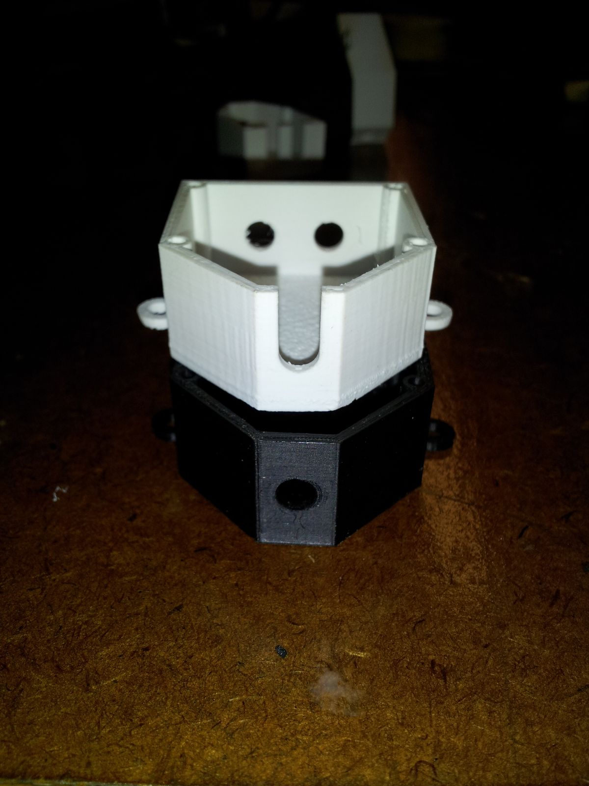

This work much better than before, but in the end I did one more redesign and decided to cut out the notches in the back instead of in the front. The cables in the back of the box are much stiffer and have a tendency to tear out of the terminal blocks instead of bending, so by putting the cutouts in the back I can still preasseble the terminal block with the back wires. Then on site I thread the box onto the cat5 through the front hole, connect up the terminal block, slide the assembly it into the box and put a lid on it.
Ultimately I ended up with this:
Installation...
Added December 21st: (way over due)
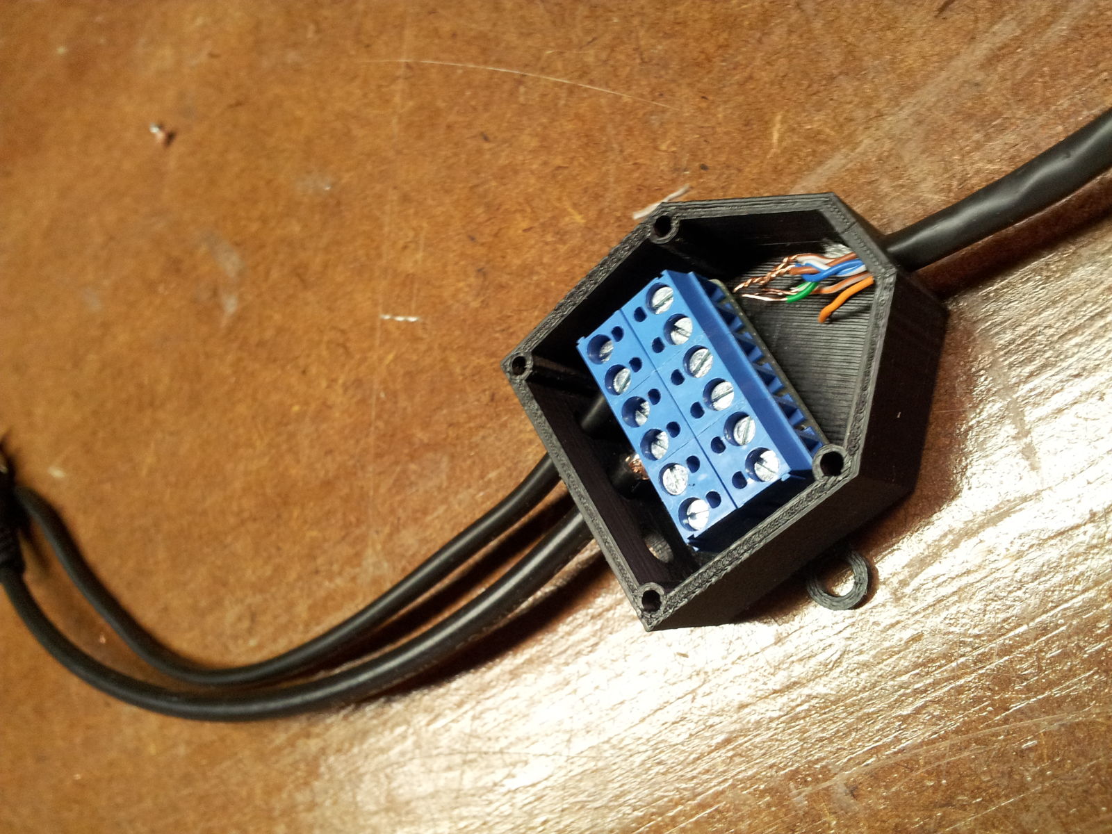
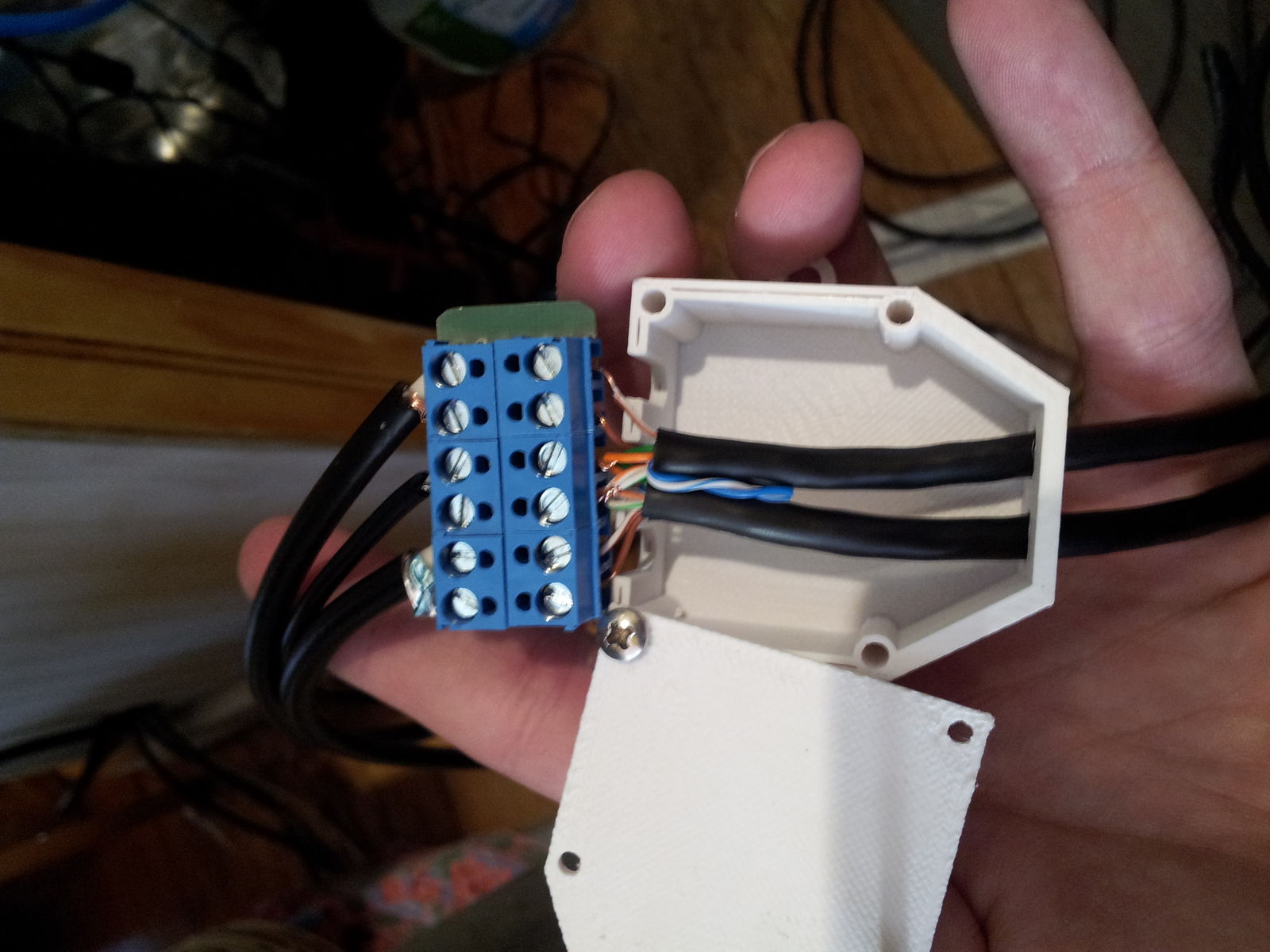
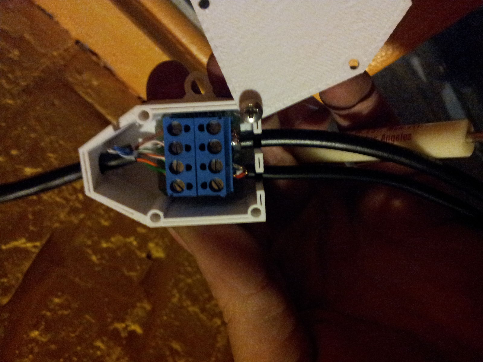
I spent some time the night before the installation preassembling the terminal blocks and the end-wires so that the installation will be quicker.(Note that I ended up redesigning the source box to have two seperate CAT5 cables come out of it instead of one, because as it turns out routing to the two upstairs cameras directly was a lot easier thanrunning to a midpoint and then split into two.
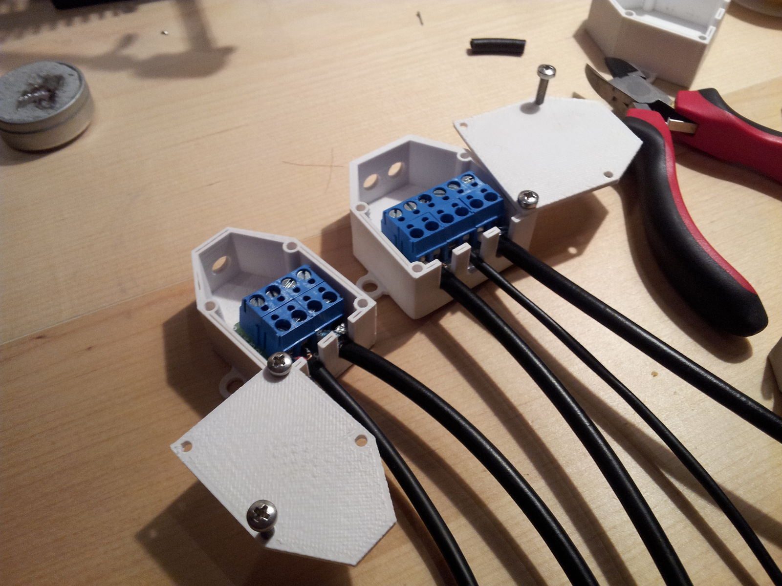
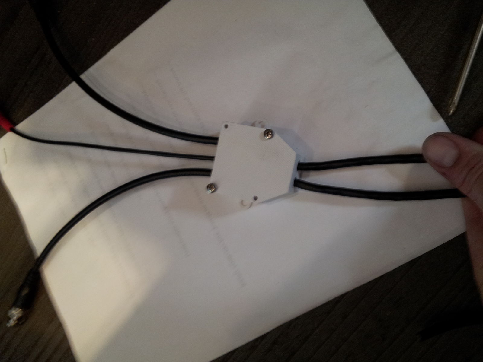
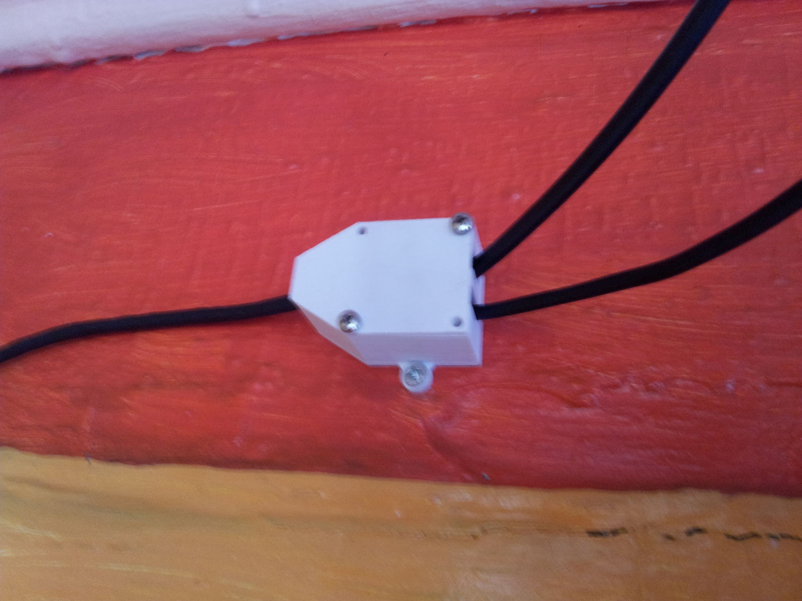
Here is a picture of the source box as I am assembling it and then another of it all closed up.
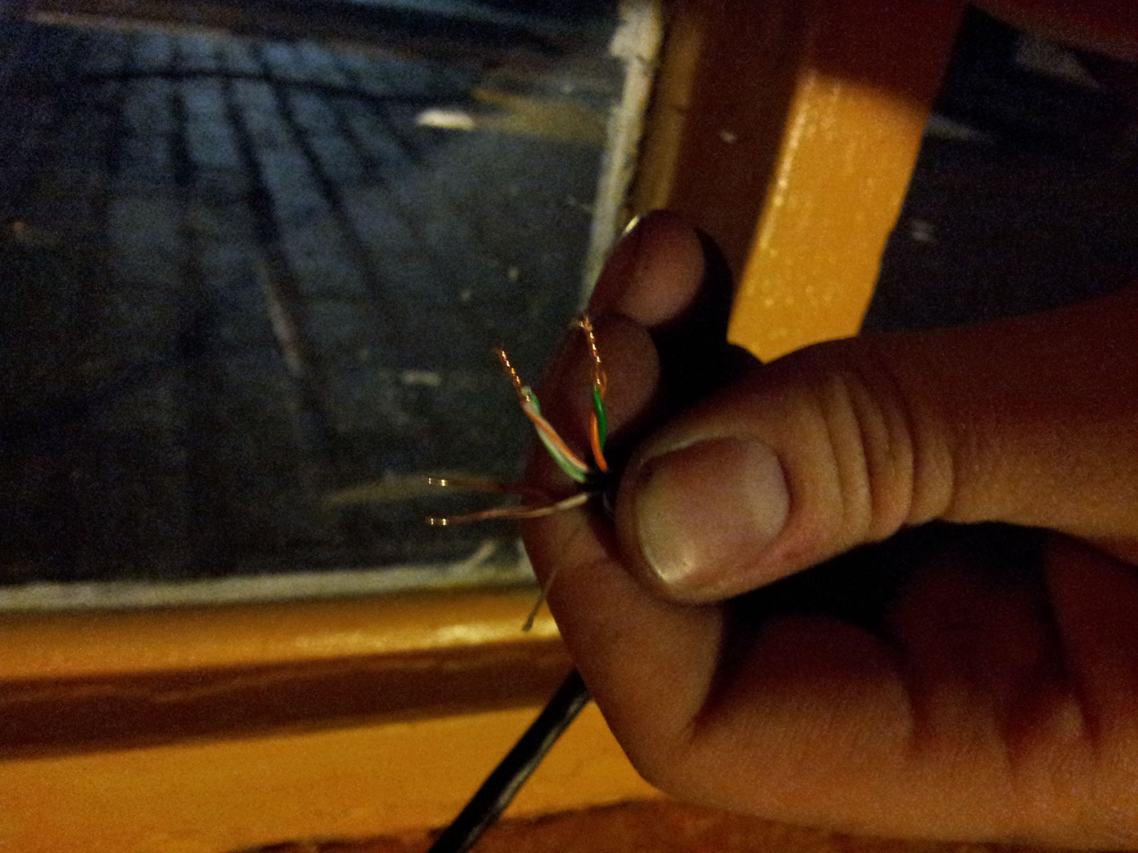
Next are a couple of pictures of the end boxes being assembled and installd.(Please excuse my terrible photos, I was balancing on a ladder.)
Outside Camera:
Conclusion.
Overall I think this turned out well in the end and I learned my fair share about designing enclosures. If I were to do it all over again, I would design the enclosure to tightly close around the cables and perhaps only use one screw to hold it all together. Also I am still a bit worried about signal loss over long distances of cat5. In my tests at the Baltimore Node I did not see any visible degrade in signal, but that may be different in the real world(to be investigate).
More Random Pictures:
printing the redesign in white:
printing the lids: